Hello friends!
Wanna share my idea about DIY low-budget, high-density drives JBOD.
Core advantages are:
high density
modular design
quiet operation
3d printed enclosure
using cheap Delta server PSUs
using cheap Dell server parts
using the SAS interface
the ability to daisy-chain
power efficiency
Specs are:
48 drives per 1 SAS SFF-8087 port
Using x1 SAS expander card (x9 SFF-8087ports) [HP 727252-001]
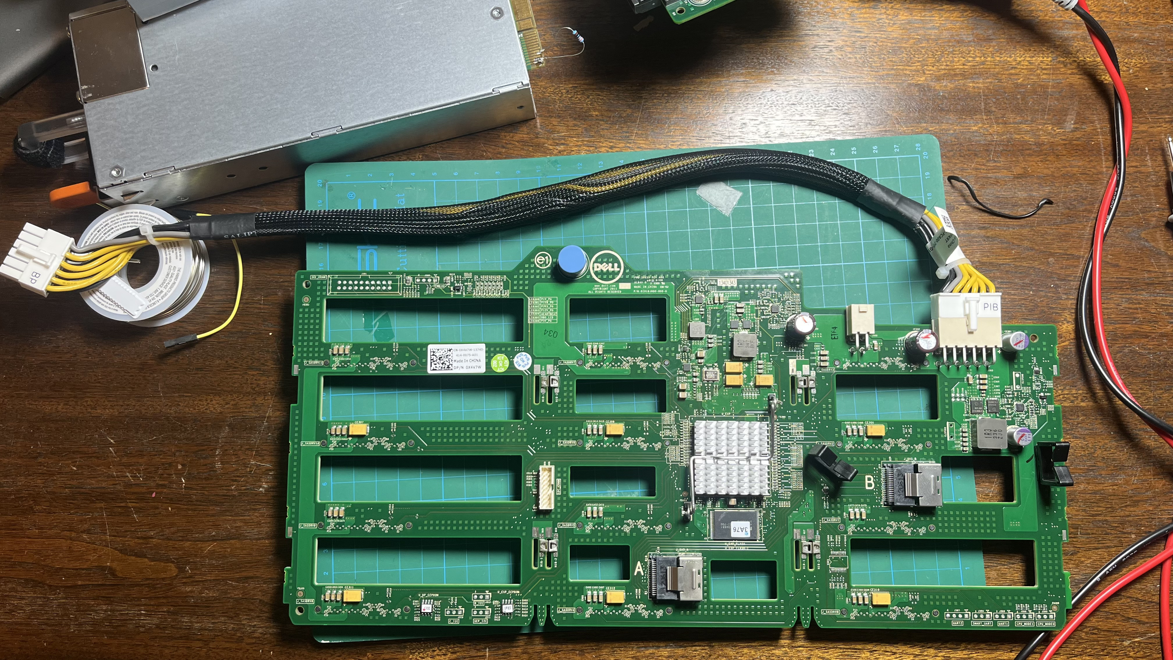
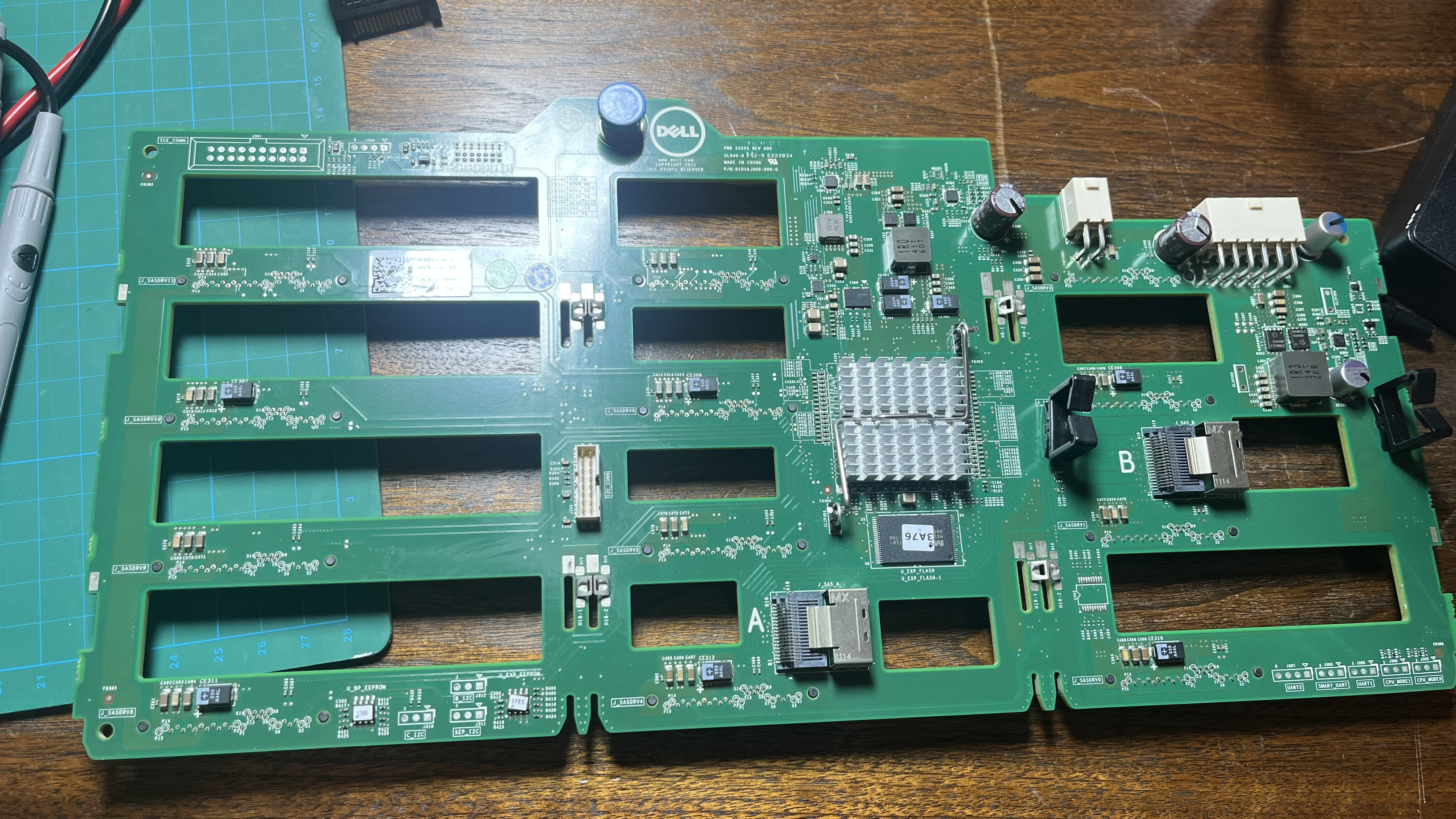
And connecting it to x4 - Dell X4V7W (12 bay LFF backplane using only x2! SFF-8087 ports per 12 drives)
And distributing power from x2 Dell MDCVH - Power distribution boards
Sound too good to be true…
LD;DL; - I failed to put it together
My assumptions and dead-ends so far are:
gray cable to the backplane is delivering 3.3v apparently it comes from Mobo because it’s just passed through the power distribution board to the signaling header which comes to/from Mobo.
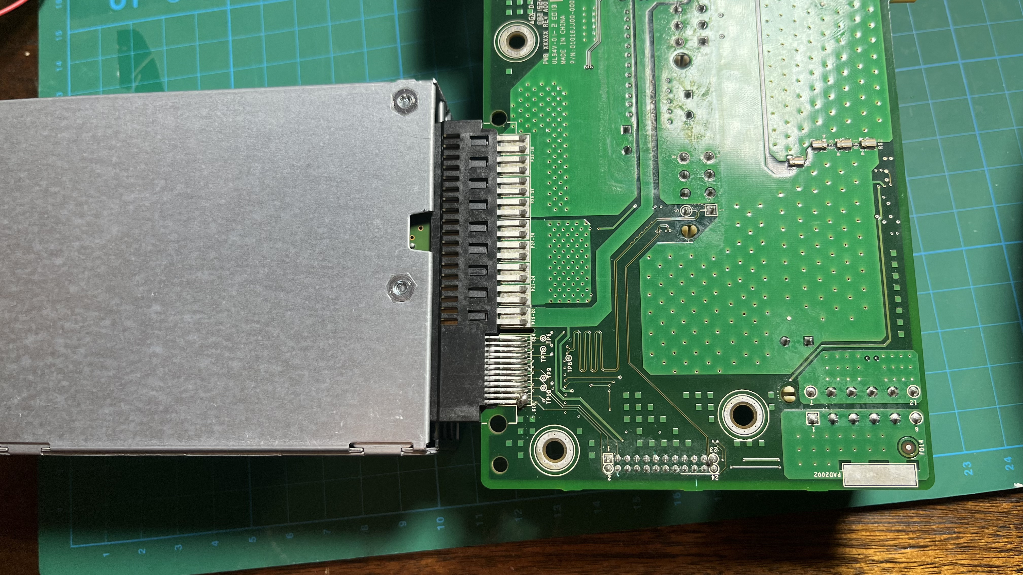
When PSU is connected to the power distribution board I could not make it to power Main 12V, only Stunby 12V is working.
TODO’s:
If I could be able to force PSU to POWER_ON state (stuck here)
making a 3.3v step-down converter board(potentially can to it by myself)
confirming the source of 5V distribution on the backplane (stuck here)
If someone could help me to sort those issues out I will make 3D models of enclosures for these backplanes with cooling, and power delivery, psu’s, but if I’ve couldn’t be able to resolve those will have to bury this awesome project…
I think it could be possible to utilize the advantage of modularity for this JBOD and assemble it for pretty cheap (200$-300$ for 48 LFF bay)
Heyyyy i did exactly that at one point. Mine worked first try. Used all dell parts wired everything for power and used a couple long 8087’s.
What seems to be the trouble?
To get the power supply to behave correctly.
I believe thiers a couple pins on the power supply’s connection that need to be soldered together… if I remember correctly. Can be done on the back of the power distribution board real clean with a bit of wire. Right under where the Psu slots in. (Jumping) a connection of the Psu. (Not just for continues power.) (that’s a different jump)
Also. Your distribution board. If u follow the traces one’s wired for continues power and one’s standby. ( I believe)
You may need to try the other power slot with the power supply. Maybe a simpler fix.
Without knowing the specific pin out it’s hard to know. But I believe on mine I soldered a couple pins on pdb. To get the 5v working.
Something like. To run the backplane it has to receive signal from processor. So without the processor u can fudge the signal jumping the signal to the 3v to the signal wire.
or something like that. Is the solution.
Deff got ya pointed in the right direction tho. Just can’t say for sure because dells proprietary crap. Built in signals for no dam reason.
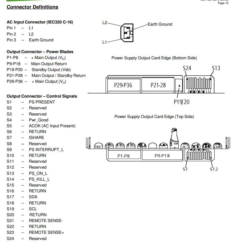
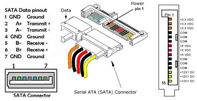
using this pinout to check the backplane voltages
I have 12V
No 5V -
No 3.3V - I have to provide this voltage on the backplane. If I’m not mistaken 3.3v has been provided by Mobo only by the original design. So I have to build a workaround for that.
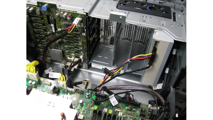
Do these backplanes, power distribution boards and cables belong together? like coming from the same system but just missing the motherboard?
what i see it his:
PSU is 12V only
Power distribution board does not seem to haven any chokes/vrms…so 12V only as well?
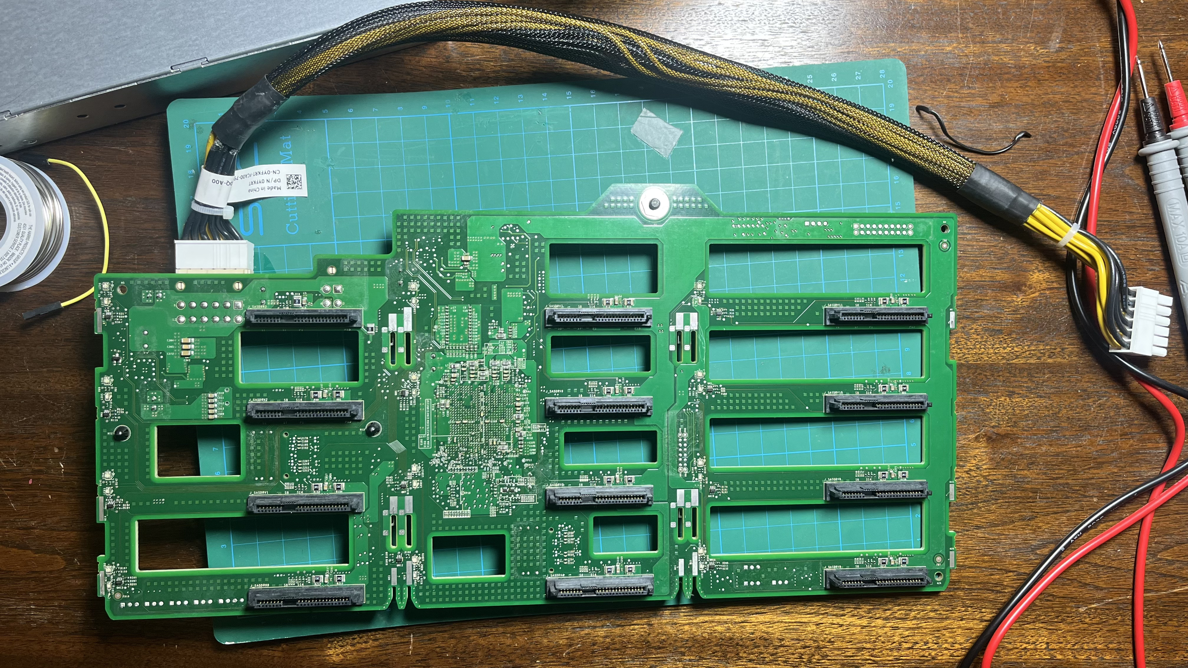
Backplane seems to have chokes, which could mean the 12v to 5v stepdown should be happening there.
but my knowledge of electronics is not good enough to positively identify that.
If the cables belongs to the backplane, I would say it provides only 12V +ground and grey is probably some sort of sensing wire. Since there is no other power connector, this again would point to the 5V coming from the backplane itself.
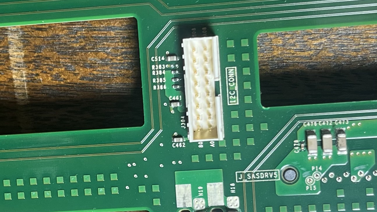
The only other option is that that little connector next to the main power, needs to get 5V from the MB?
(Color coding in server parts, while not entirely reliable, is usually solid. Black is ground, yellow is 12V, red is 5V)
3.3 volt is usually not needed to power sata/sas drives. So unless the board uses it, you don’t need it.
My best guess here is that either:
some sort of signal is missing that tells the backplane to turn on properly. And this might be the 3.3V you are talking about
5V power should come from the MB with an extra power cable
If you find out where to supply 5v (or 3.3) you can use buck converters for 12v to 5v, like the ones I used here:
that was my thoughts either about 4-pin connector, but after deep dive into documentation, I’ve found out its powers the front panel dvd/tape drive, etc.
I have a working T620 system those parts belong to it.
if 3.3v is not mandatory I will focus to trace 5V source.
About the ground cable, after I’ve managed to turn in PSU_ON state I found out its actually ground as well but it’s ground only when PSU is in PSU_ON state not a STAND_BY mode
most likely will do nothing, but I think it’s at least worth a try. Connect up a hba, maybe it can sense that way if there is a connection or not.
Other than that, I would advise to also post on some hardware/server forums if you haven’t done so already. Might be as simple as grounding another pin somewhere
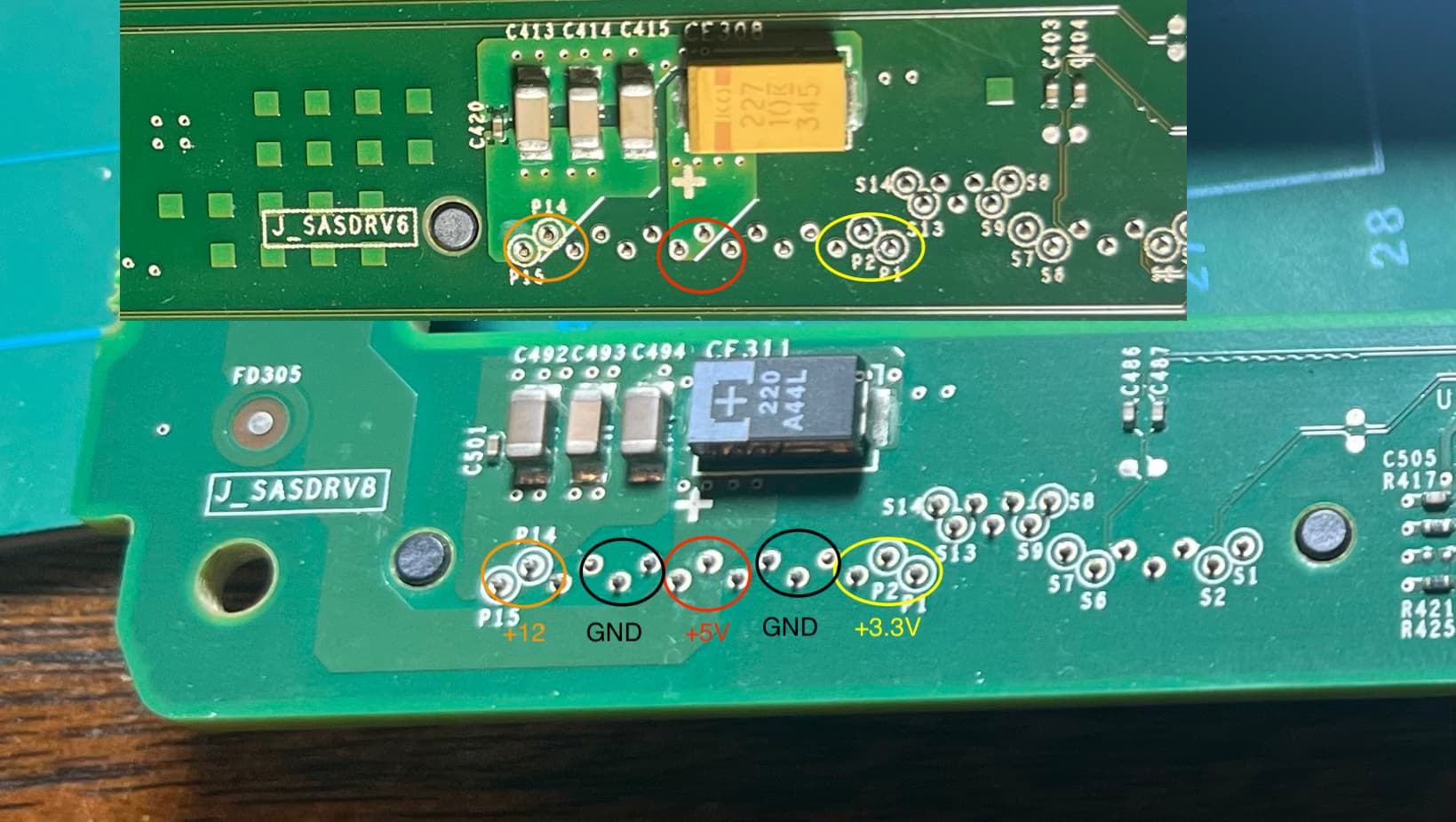
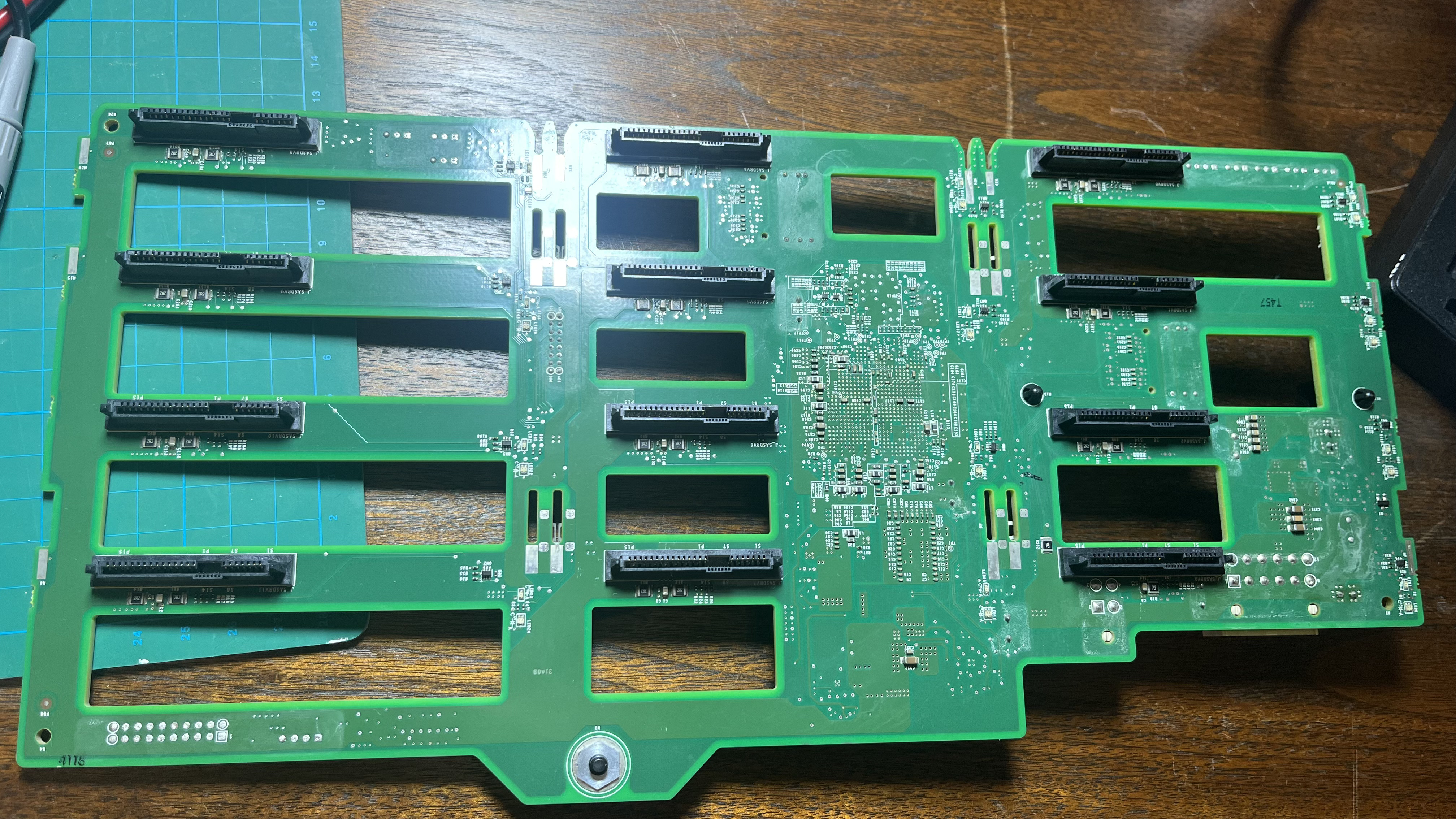
On the back of backplanes I found those modules connected to 5V line, idk what are those.
My bet is 3 same brown components its a resistors, my tested shows they are 3 Mega Ohms each, small one is 3 Mega Ohms aswell.
Idk what is yellow or black component on board I would say its a diode.
So probably its capable to convert 12V to 5V on backplane PCB.
But for now on 5V lane I have only 0.061V(top backplane) or 0.071(bottom backplane)
From mobo comes the signaling header, unfortunately, I couldn’t find any docs about it.
The only way I can see for now is measuring currents from mobo on the working machine… (that’s scary af)
to get an idea of how to turn this thing on…
You should give up on the dell stuff. Much simpler to use an HP DL380 G8 expander backplane which just needs 12v input power and a single 8087 connector plugged in.
The higher density JBODs are the most expensive. For small JBODs I think it’s easier to go the refurbished route, but if you’re going to push past 48 or more drives it can be worth it. The 90 drives 4U are insanely dense at easily more than a Pb per server and 10Pb per rack.